
Opportunity cost
- Todd Morris

- Jun 6
- 8 min read
Updated: Jun 22
I've had my Penn Central C628 for quite a while. I think I bought it as an undecorated model, assembled, painted, added DCC and weathered the thing myself. I even patched out the Penn Central decals and added CR patches intentionally. A labor of love, and I did like the weathering - inspired by plenty of pictures of grimy and rusty bankrupt locos of the rainbow years of Conrail. 6751 probably would have been a mainstay in my fleet for many years, but I started to have a problem with it... Heat buildup from a resistor on the circuit board started melting the shell. I got worse a few months ago, and a portion of the roof collapsed due to heat. Couple of pictures:


My original thought was to buy a new shell for it, but they I got to thinking that the new shell might meet a similar fate if I didn't do something about the board....
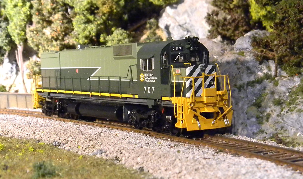
Went hunting on the Bowser website, which is extensive in terms of parts. Put a new C628 shell in the cart ($15) and a couple of sets of handrails (which are always flying off the front corners of these beasts) for another $30. Then I ran into a fully assembled Bowser Executive Line M630 shell in British Columbia Railroad livery (the multi-green version) for $45! Hard to pass up, and I quickly dumped the contents of the cart and added it. I didn't want to burn that one up, and I located a Executive Line version 1 circuit board for $10 on ebay. Note: I've subsequently found that TCS makes a replacement board that has at least as much capability as this one, although this one uses an 8-pin rather than the newer 21-pin decoder.
Couple of problems.... The M630 had a different fuel tank than the C628 AND rode on Hi Ad trucks which were not (although the trucks had three axles) anything like the C628 Tri Mount trucks. Bowser was selling preassembled truck sets (2) for $50.... Alright, I bit.
Gutted the old C628, took the old shell off, fuel tank off, trucks off, circuit board out. Added a piece of breadboard over the motor mount to serve as a platform to secure the new circuit board and decoder, and removed one of the circuit board platform supports to use the tapped holes for supporting struts for the breadboard:

The photo above shows the breadboard supports but also the new fuel tank and Hi Adhesion trucks.
Installed the new trucks that I received from Bowser and found out something was wrong with them - the three axles of the front truck wouldn't sit flush on the track. Ended up having to take that truck apart (at least the truck sideframes) and discovered that one of the brass wipers was deformed and was the reason the truck wouldn't ride flat. Persuaded the wiper back into the correct shape and eliminated the problem. Those trucks also didn't have half of the brake chambers, so Bowser is going to send me brand new trucks (hopefully not deformed or missing parts!). The fuel tank is also slightly different than the Stewart version, and although the fuel tank side panels slide into a housing that is secured to the frame, that housing must be about 1/16" longer than the Stewart version. Because I didn't buy that housing, I ended up shearing off the back end of my housing and gluing the panels on and trimming off the excess plastic.
Next hurdle was produced when I tried to push the shell down onto the chassis. The Bowser version air tanks are now on the shell (not slotted into the fuel tank sides) and among a couple other items, interfere with closing the shell on the chassis. Had to get my Dremel out and modify the metal frame in some areas to get it to fit - of course having to remove trucks before I did it. After about an hour of trial and error here's the shell on top of the frame... I'll have to repaint the frame where you can see the edges.

Then there's the version 1 circuit board. No documentation on it, and Bowser doesn't know what the wiring is for any of the plugs on the board. Trial and error... Here's a shot of it out of the package in which I received it:

The white arrow points to the light output connector (J3)... The only pins actively attached to the decoder (the blue arrow points upward to the blank 8-pin plug where the decoder would go) are pins 2 (Front headlight - white wire), 3 (Rear headlight - yellow wire), and pin 5 (the positive wire for all of the lights) - found this out by tracing connections between the DCC plug and the lighting connector with a multimeter. The other pins are accessible from the underside of the board (more on that later). The blue arrow pointing from the top is the motor connections (MJ) (I reused the plug and wires), and the two other blue arrows point to the track pickups (J1 and J2). Reused one of the two plugs and sets of wires.
In terms of setting up the track pickups and motor connections, mostly just joining wires via solder and shink-tubing over the junctions. Plugged in a Digitrax DH142 with an 8-pin harness. Note: the "4" in DH142 means there are 4 functions available - (2 of which are for directional lighting), which the remaining two planned for the ditch lights and the class lights. More on lights later. Ran it on the track and ensured that "forward" and "reverse" corresponded to the appropriate yellow and white wire outputs for lighting.
Lighting is a bit of a nightmare. This pre-made shell is fully populated with boards for headlights, taillight, ditch lights, number board lights and class lights and there are a grand total of 3 connectors provided - one of which is a 6-pin connector that mates with the circuit card. However, by my reckoning, this means only the rear headlight will receive the positive voltage line. The other plugs must mate to a more recent circuit card. To use this one, I'm going to have to improvise and rewire the lines in these other plugs once I figure out the purpose for each.
Another tidbit... This circuit card is too wide to fit inside a Bowser C628/630/636 shell. I ended up taking it to my belt sander and shaving off as much circuit card as I could and still preserve functionality. The positive lighting channel was also intermittently connected and I ended up jumpering the underside of the board between the blue decoder output and pin 5 of the lighting connector. After trying out that rewiring I blew out a resistor for the rear headlight.... argh. My two extra channels (the green and purple wire coming out of the decoder) also need to be routed to pins on the lighting connector through a 1k Ohm resistor. Got down to some close work with the soldering iron... I'll show you the carnage soon...
Well, here's the revised underside of the circuit board - run through of the + side, three new resistors for FOR, F2 and F3... Hope the all work.

Put Humpty Dumpty back together again to determine if I had enough space in the shell, and I think we're good. Here's a shot with the unit on the rails without the couplers (which should tighten everything up when it's all done. I'm probably getting a bit ahead of myself since I'm supposed to get replacement trucks from Bowser early this week.
Lights! let there be lights! Now that I'm motorized, forward is forward, reverse is reverse, it's time to try to understand the color coding of wires, their function and their location. There is a 6-pin connector that will mate to the circuit board - that's going to function as the home base for the light outputs, and I know that pin 1 will control the F1 function for this locomotive (on and off light feature for something - most likely the ditch lights), pin 2 will control the front headlight, pin 3 the rear headlight depending on the direction of travel for the locomotive through F0, pin 4 will be empty, pin 5 will be the + supply voltage for ALL of the lights, and pin 6 will be the F2 function (most likely the class lights). The current 6-pin connector is populated with a black wire that goes to the roof of the cab. My guess is that this is intended to be the off/on for either the class lights or the number board lights. Pin two is a yellow wire that runs to the nose of the loco and probably is the on/off for the front headlight in the nose. Pin 3 is a blue wire that goes to the negative terminal of the rear light circuit board (on/off for the rear headlight). Pin 4 is open and pin 5 has a red wire that feeds the + side of the rear light circuit board (but does not power any other light board). Finally pin 6 is an orange wire that runs to the front light circuit board in the nose, and I suspect controls the ditch light on/off. So, if I'm right, I should get about 90% of what I'm looking for if I can determine which wires in the two other provided connectors are meant to be the + voltage feeders for the front circuit board and the cab roof circuit board. In the case of the front circuit board, if my assumptions are all right, the only available wire would be the red one there (which jives with the red wire going back to the rear circuit board). That wire leads to the 5-pin connector along with a green wire that goes up to the cab roof, but it's not located in the same pin on that connector, which leads me to think that the green wire is for a function on/off up there. The red line that goes up to the cab roof is a more likely possibility for the + supply voltage line. At this point, I'd be guessing. Until Bowser comes back and says "can't help you with that", I'll wait.
Bowser answered the bell! I got a diagram of the real circuit board that would go with this shell.

Wish I would have had this sooner, but the mysteries are much smaller now. The bottom connector is the light output 6-pin connector I have on my board. Front headlight is on pin 2, rear headlight pin 3. + side of all lights is pin 5. The other two lighting connectors also have + side of lights on 5 available pins (only one of which in each connector is populated with a red wire). the other pins are for the - side of each light (the switch). Now I just need to figure out which wire goes to each function...
Here's what I found out through trial and error. Aux 1 (black) is hooked up to the white class light (F1), Aux 3 (orange wire) to the ditch lights (F2). On my Prodigy Express, F2 is a momentary function, which means unless I make some reassignments, I'll have to hold F2 down as long as I want ditch lights. The green wire is for the green class light and the blue I guess for the red class light. Finally, the other black wire is for the front number boards and I joined that to the front headlight circuit.
I have to start thinking about weathering this beast - on a whim I think I put weather BCR M630 and found this artist rendering, which I think is a great start: krys-halamic-m630-bcr-early-2-pack.jpg (1918×1024).
I'm not sure what the genesis is for the website, but I think I've seen this guy's other work, and it's a great place to get ideas for weathering projects.
Finally got my replacement trucks from Bowser and installed them. Note to self - make sure you have the track pickups as the same color wire on each side if they have pre-built cable connectors. The connector is expecting the right polarity based on which rail it's picking up power from. Started the weathering process by hitting the underframe, trucks and fuel tank with a variety of black and gray paint hues.

We'll do a little time lapse of the progress through pictures:


Up and running and leading a consist shortly I predict. I do want to get some longer couplers for it.
Turns out I was a bit premature. Had it on the track last night and wanted to move it - ran it at speed forward, it moved a little and stopped and would not run. When I rusted up the wheels I got a bit too much paint on the ends of the axle and the surfaces that mate up with the wipers. After removal of the truck sideframes, some filing and a bit of running, it's running pretty well.
Comments